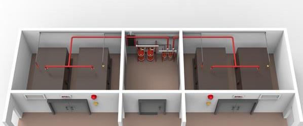
Gas fire extinguishing system nozzle installation requirements?
Gas fire extinguishing system nozzle installation requirements? We all know the importance of fire knowledge, today the fire company affiliated enterprise Lin Feng Mai here will introduce some about fire knowledge for you, only understand the relevant fire knowledge, we do fire engineering, fire construction can be more handy. Understanding fire knowledge, so in daily life, will also subconsciously pay attention to related fire equipment, which may save our lives at some point.
Nozzle installation
1. When the nozzle is installed, its model, specifications and nozzle direction should be checked one by one according to the design requirements.
2. For the nozzle without decorative cover installed under the ceiling, the thread of the connecting pipe end shall not be exposed to the ceiling; The nozzle with a decorative cover installed under the ceiling shall be close to the ceiling.
Installation of prefabricated fire extinguishing system
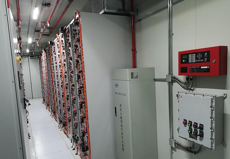
1. The installation position of prefabricated fire extinguishing system such as hot gas sol fire extinguishing device and its controller and sound and light alarm shall meet the design requirements and be fixed firmly.
2. The space environment around the prefabricated fire extinguishing system device meets the design requirements.
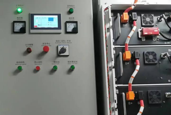
Installation of control components
1. The installation of the fire control device meets the design requirements, and the installation of the fire detector in the protection area meets the provisions of the national standard "Code for the Construction and Acceptance of automatic fire Alarm System" GB 50166.2. The manual and automatic switch set in the protection area shall be installed at the easy to operate part of the entrance of the protection area, and the installation height shall be 1.5m from the ground (building) surface of the center point.
3. The manual start and stop buttons are installed at the easy to operate part at the entrance of the protection area, and the installation height is 1.5m from the ground (building) surface of the center point; The sound and light alarm device in the protection area is installed in accordance with the design requirements, and is firmly installed without tilt.
4. The gas emission indicator should be installed directly above the entrance of the protection zone.
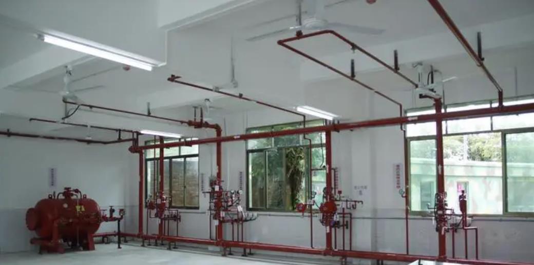
First, heptafluoropropane fire extinguishing system, ig541 mixed gas fire extinguishing system:
1. The calculation results of the working pressure of the sprinkler nozzle head of the heptafluoropropane gas fire extinguishing system shall comply with the following provisions:
Primary pressurized storage vessel system Pc≥0.6 (MPa, absolute pressure);
Two-stage pressurized storage vessel system Pc≥0.7 (MPa, absolute pressure);
Three-stage pressurized storage vessel system Pc≥0.8 (MPa, absolute pressure).
2, the equivalent nozzle area should be calculated according to the following formula:
Where Fc -- equivalent nozzle area (cm2);
qc -- equivalent orifice injection rate per unit area [kg/ (s?cm2)] can be adopted in accordance with Appendix C of this specification.
3. The actual orifice area of the sprinkler nozzle head shall be determined by test, and the specifications of the sprinkler nozzle head shall comply with the provisions of Appendix D of this specification.
4. In general, the flow coefficient of the sprinkler nozzle head is only determined by the nozzle port structure when the working medium is in a certain turbulent state. However, for the sprinkler nozzle head of the HFC-227E fire extinguishing system, part of the nitrogen will be dissolved in HFC-227e, which will affect the flow rate of HFC-227E during the spraying process because the system adopts nitrogen pressurization transportation. The amount of nitrogen dissolved in the working process of the system is related to the amount of precipitation and the pressurization pressure of the storage container and the working pressure of the sprinkler nozzle head. Therefore, the flow coefficient of the sprinkler nozzle head of the HFpropane fire extinguishing system, that is, the actual equivalent port area value of each nozzle, is related to the pressurization pressure of the storage container and the port structure of the sprinkler nozzle head, and should be determined by test.
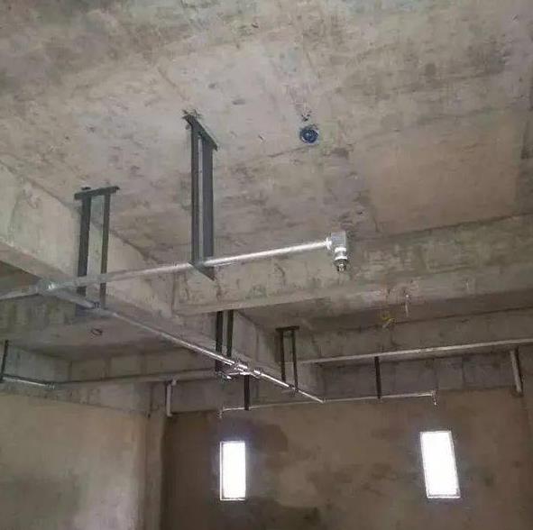
Second, ig541 mixed gas fire extinguishing system:
1. The calculation results of the working pressure of the sprinkler nozzle head of the IG541 mixed gas fire extinguishing system shall comply with the following provisions:
Primary pressure (15.0MPa) system, Pc≥2.0 (MPa, absolute pressure);
Secondary charging (20.0MPa) system, Pc≥2.1 (MPa, absolute pressure).
2, the equivalent nozzle area, should be calculated according to the following formula:
Where Fc -- equivalent nozzle area (cm2);
qc -- equivalent orifice injection rate per unit area [kg/ (s·cm2)], can be adopted in accordance with Appendix F of this specification.
3. The actual orifice area of the sprinkler nozzle head shall be determined by test, and the specifications of the sprinkler nozzle head shall comply with the provisions of Appendix D of this specification.
Third, high pressure carbon dioxide fire extinguishing system:
1, the sprinkler nozzle layout of the total flooding fire extinguishing system should make the carbon dioxide distribution in the protection area uniform, and the sprinkler nozzle should be installed close to the ceiling or roof.
2, set in places such as dust or spray painting, should add a dust cover that does not affect the spray effect.
Four, gas fire extinguishing system nozzle design general provisions and installation requirements
1, the protection height and protection radius of the sprinkler nozzle should comply with the following provisions:
(1) The maximum protection height should not be greater than 6.5m;
(2) The minimum protection height should not be less than 0.3m;
(3) When the installation height of the sprinkler nozzle is less than 1.5m, the protection radius should not be greater than 4.5m;
(4) When the installation height of the sprinkler nozzle is not less than 1.5m, the protection radius should not be greater than 7.5m.
2. The sprinkler nozzle head should be installed close to the top of the protection area, and the maximum distance from the top surface should not be greater than 0.5m.
3, when installing the nozzle, it should be checked one by one according to the design requirements of its model, specifications and direction of the spray hole, check the quantity clearly, and avoid the lack of quantity affecting the construction progress.
3, the nozzle installed under the ceiling without a decorative cover, the connecting pipe end thread should not be exposed to the ceiling; The nozzle with a decorative cover installed under the ceiling, the decorative cover should be close to the ceiling.


